This is the third in a series of articles about using microcontroller devices with e-paper displays for displaying dynamic calendars.
The custom Featherwing described in this article is available for purchase on Tindie.
I wanted to create a few projects interfacing an e-paper display with the Adafruit HUZZAH 8266 and HUZZAH 32. The HUZZAH microcontrollers are a great fit with e-paper displays. In addition to having WiFi connectivity to grab date, weather and calendar information from the internet, they also can power themselves down and wake up at a later time. Since the e-paper displays retain their display without power, this makes for a great symbiotic relationship. Running the HUZZAHs with the e-paper display for just a few minutes each day can allow the device to run for weeks or even months depending on the size of the battery.
The initial problem I had is that the Waveshare displays require 8 wires to connect to the HUZZAH for the SPI interface and power pins. In addition, I wanted to add a reset button that will wake up the Feathers from their deep sleep as well as have one or two programmable buttons. This could have been done with a Proto Featherwing, which provides a mini-prototyping board for components, but the number of wires to solder for the e-paper display and buttons requires a lot of wires to solder in a small area. I decided to see if I could design a custom Featherwing that not only could handle the e-paper interface and the buttons but also be compatible with both the HUZZAH 8266 and HUZZAH 32.
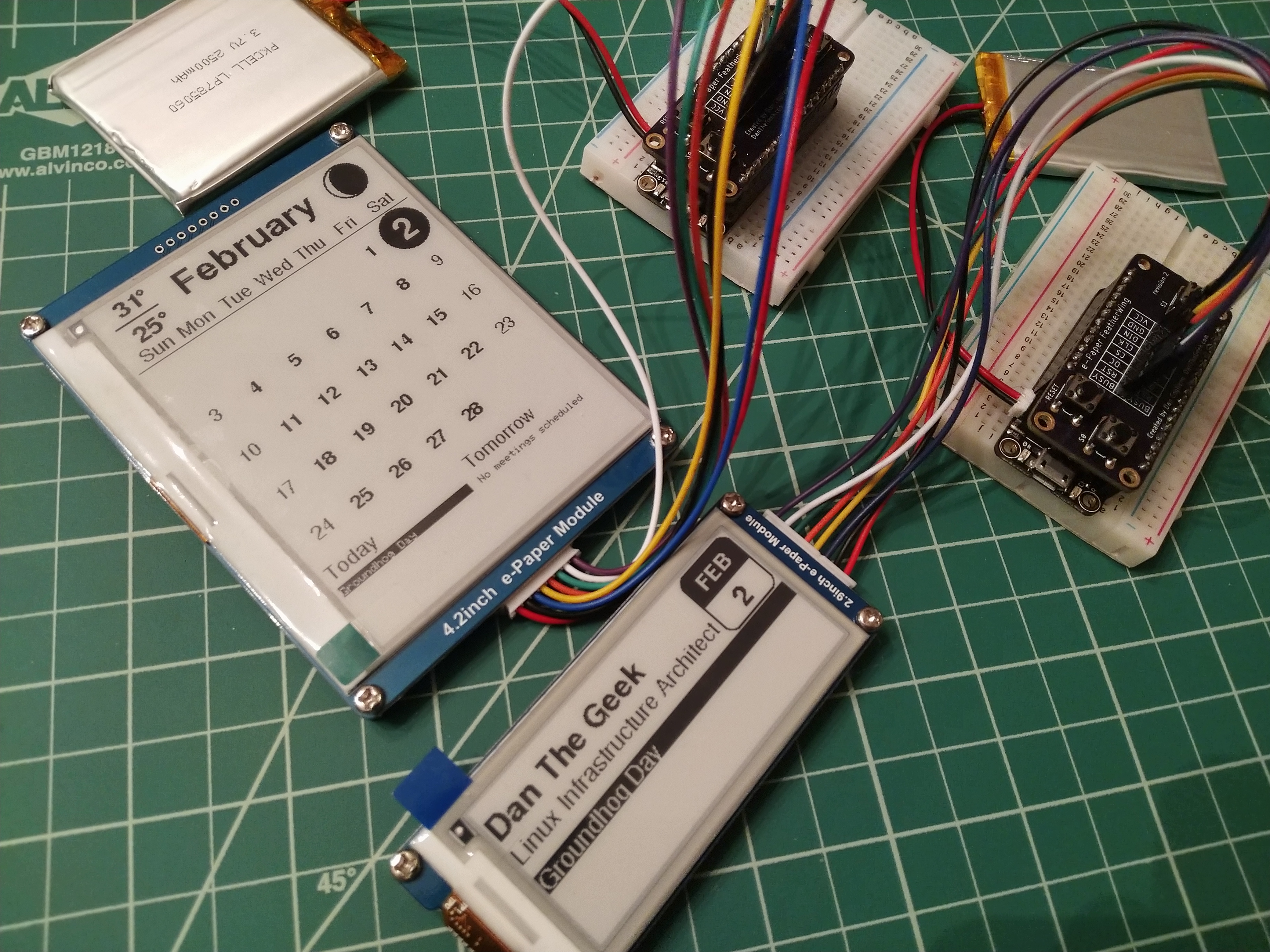
Prior to creating the custom Featherwing, I plugged the e-paper display wires into the HUZZAH directly with the cable provided with the Waveshare display. This method can be used instead of the custom Featherwing but does not allow for the extra buttons, but it is a good method for testing. Since the supplied cable uses female connectors, you may need male jumper wires to connect to the female headers like I did.

The first task was to map out the e-paper display pins on both the 8266 and 32 so the same physical pin locations on the Featherwing will work on both. With some research, I came up with these pin definitions for the e-paper display:
#if defined(ESP8266)
	// Feather HUZZAH 8266
	#define RST_PIN        15
	#define DC_PIN          2
	#define CS_PIN          0
	#define BUSY_PIN        4
#else
	// Feather HUZZAH 32 (same physical locations as 8266 but different IO pins)
	#define RST_PIN        33
	#define DC_PIN         14
	#define CS_PIN         15
	#define BUSY_PIN       23
#endif
The Waveshare e-paper display library will need to be updated for these pins. You can find the pin definitions in the epdif.h file in the library.
Similarly, I mapped out the buttons so they would physically match with both Feathers. This is what I came up with:
#if defined(ESP8266)
	// Feather HUZZAH 8266
	#define BUTTON0 12
	#define BUTTON1 5
	#define LEDPIN 0
	#define LEDPINON LOW
	#define LEDPINOFF HIGH
#else
	// Feather HUZZAH 32
	#define BUTTON0 12
	#define BUTTON1 22
	#define LEDPIN 13
	#define LEDPINON HIGH
	#define LEDPINOFF LOW
#endif
Due to fewer GPIO pins available for use on the 8266, I had to make a compromise with the buttons. Button S1 required mapping its pin to a pin used for the I2C interface. This is really not a problem for the e-paper display since it is using an SPI interface, but if there are other Featherwings installed that are using an I2C interface, you may wish to leave out the S1 button ( or avoid pressing it!). The other buttons worked without issue.
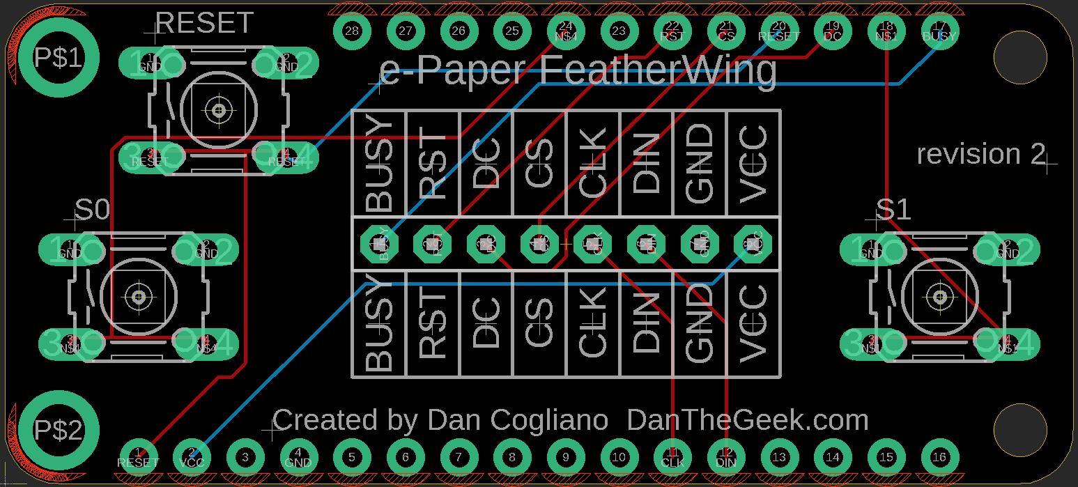
Here is a layout of how the pins are used with the Featherwing. The Adafruit HUZZAHs are the only Feathers so far that have been tested.

The wiring for the Featherwing is straightforward and uses all through hole components. The e-paper interface uses male header pins just like the rest of the board, but facing up instead of down. The three buttons are 6mm tactile buttons that can be purchased from Adafruit. Here is an example of how to code for the buttons:
pinMode(BUTTON0, INPUT_PULLUP);
if ( digitalRead(BUTTON0) == LOW )
	Serial.println("button 0 detected");
In keeping with the compatibility between the 8266 and 32 boards, I also made LED pin definitions that would work with both boards. Since the 8266 uses the pin in reverse from the 32, LEDPINON and LEDPINOFF defines were added to make the code work with either board.

Using Autodesk Eagle
I’m no expert with using Eagle, or in PCB design for that matter. In fact, this is only the second PCB board I have designed, and the first was a custom Featherwing for another project. Designing a custom Featherwing, however, was pretty easy, due a couple factors:
- Featherwing and button schematics were available in the parts library
- Simple board layout
- Use of through hole components (for easy soldering)
The schematics availability in the parts library was a big time saver, which saved me from entering the dimensions of the Featherwing and all the hole placements from scratch. After watching a few videos to learn how to use Eagle, I moved from importing the components from the parts library and connecting wires in the schematic to switching to the PCB board view and routing wires.
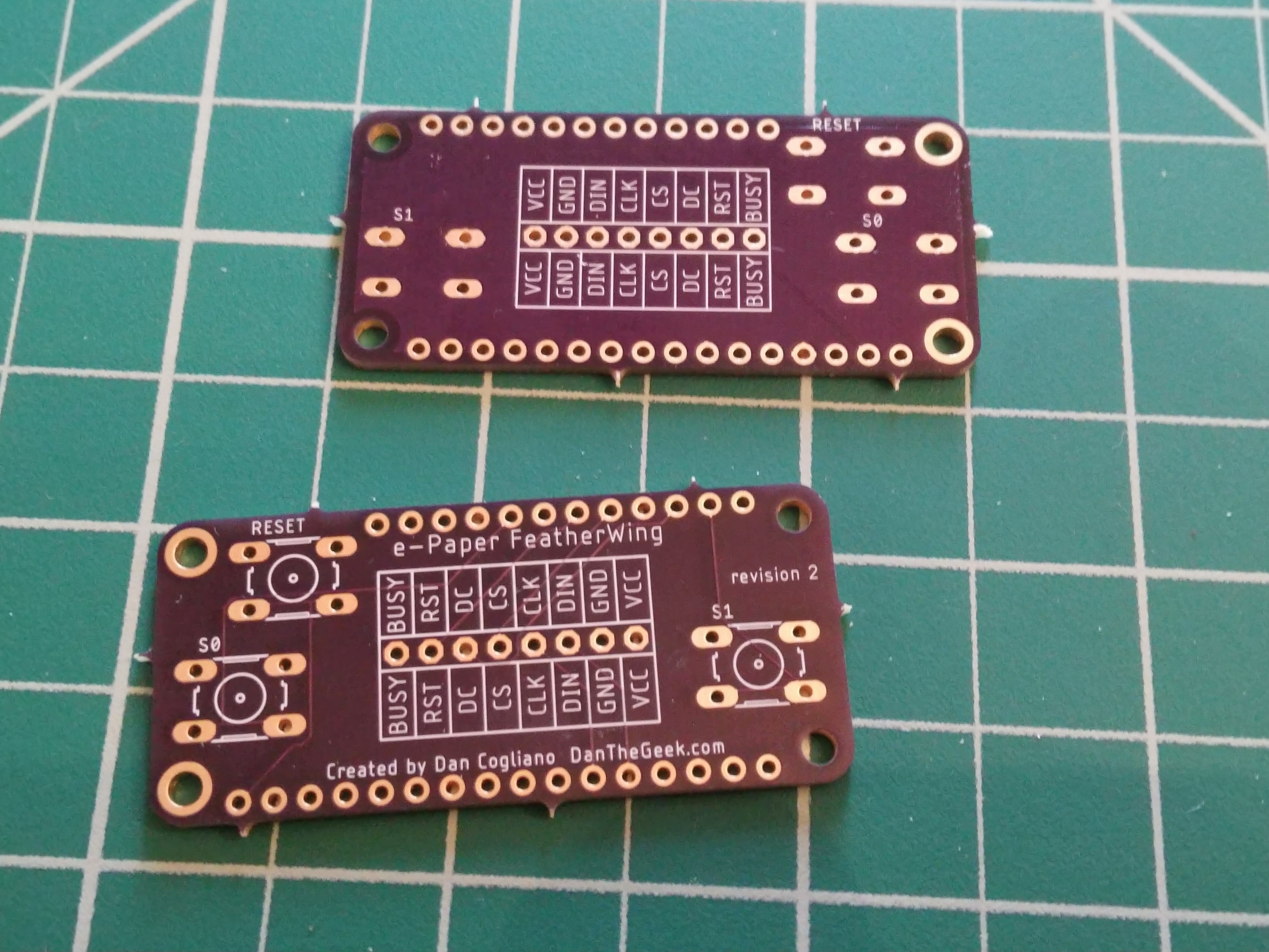
I then added the silk screening to label the pins, buttons and other text. I duplicated the pin labeling on the bottom in case I wanted to wire the Featherwing below the HUZZAH instead of the top. I then sent the design off to Oshpark.com for fabrication.
Putting It Together
Putting it together requires just some male headers and optional buttons. You could also use female headers if you want to put the board below the main feather board. Adafruit has a great tutorial on how to solder headers onto a Feather. The e-paper interface is just 8 header pins pointing up, so you will need to solder it from the bottom. I would recommend soldering the 8 header pins before soldering the buttons, since the buttons can get in the way a bit if put the header pins in a breadboard to secure them for soldering.
Summary
In all, I was very happy with the result. I no longer need to hand solder a dozen or so wires on a small proto board and the final product looks very clean. Having the same board compatible with both the HUZZAH 8266 and HUZZAH 32 is an extra bonus. I am putting the finishing touches on the code for a monthly calendar display and name plate/badge that you can see in the photo at the top of this article. This code will be released to GitHub and described in a future article.