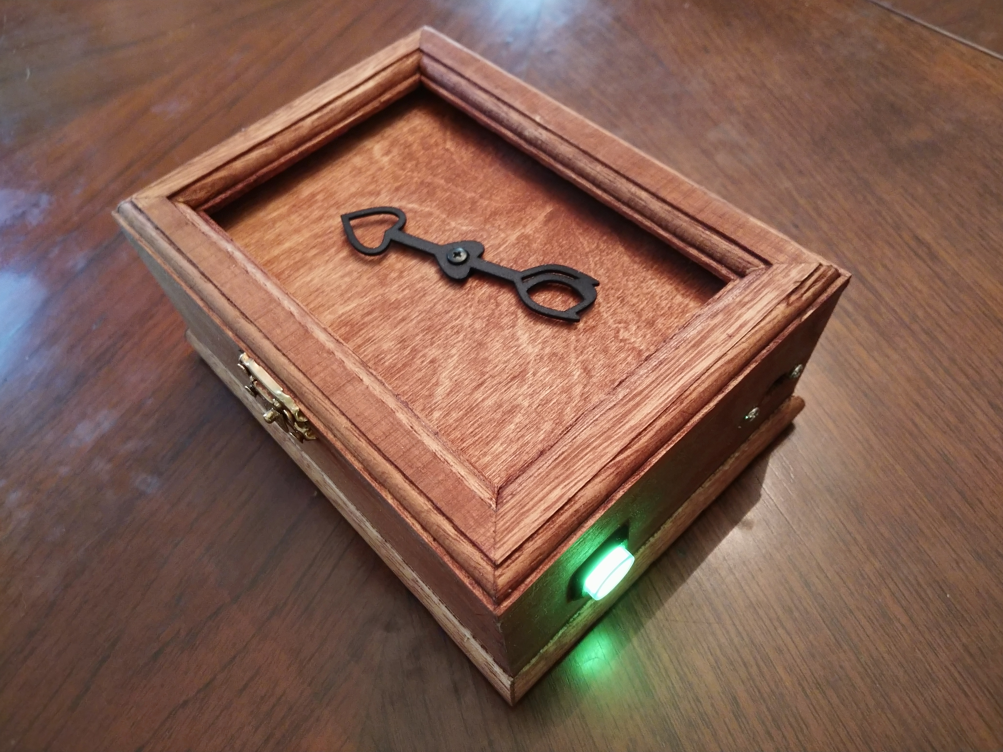
I found the personal compass project at Instructables.com quite interesting. Basically, a personal compass works like a regular compass, but instead of pointing to magnetic north, it points to a particular location of personal interest. Maybe it is pointing to the place where you were married, perhaps where your childhood home is.
All this compass magic is done using an Arduino with a compass (magnetometer) sensor, GPS module and a servo motor to point the way. However, there were a couple of things I didn’t like about the original project:
- Extra gears were needed to increase the servo’s sweep to 360 degrees
- Location was hard coded into the code
The extra gears complicated the build and it still had to “rewind” itself when it reached its 360 degree limit, so I decided to use a continuous servo with feedback. This allowed for full 360 degree rotation and beyond of the compass needle. The feedback wire is used to determine where the pointer is located so it can be positioned at the correct angle. The one drawback for the continuous rotation servo with feedback is that there are not that many available, and the only one I found required 5V to run, even with no load on the servo. So, I added a 3V to 5V booster module to get the servo to work with the 3V battery power.
To solve the hard coded position issue, I decided to go with an ESP32 based Feather processor from Adafruit, the HUZZAH 32. This processor includes WiFi and Bluetooth features. I didn’t really need the processor to connect to a WiFi network or Bluetooth, but its web server feature provided a way to save configuration settings like the location’s coordinates from a cell phone quite easily. While I was at it, I wanted to add a smart button feature.
My code for the improved personal compass and supporting applications can be found on GitHub.
The Smart Button
The ESP32, along with it’s ESP8266 sibling, has a deep sleep mode that can be used to programmatically power up and down the compass. This method does not fully power down the unit like a true power switch, but it shuts down most of the processor and the power drain is very low. So instead of incorporating an on/off switch I used a momentary switch for the project. This allows for greater flexibility and allows the switch to work in different ways depending on when and how long the button is pressed. I came up with these uses for the switch:
- Short press – Use to turn the unit on or off. The unit actually enters deep sleep mode instead of being turned off. The Adafruit GPS module and Power Boost modules do not shut down by default when deep sleep mode is entered, so the enable pin on each module was used to send a signal to shut down just prior to entering deep sleep.
- Long press during boot up – Use to define locations (using a web page from a smart phone)
We can also power down the unit automatically after a set period of time to conserve the battery.
The LED was programmed to blink while acquiring the GPS location, switching to steady on when the GPS location was found. It also blinks to indicate you have arrived at your destination (when you are within a specified zone radius of the destination), and when it is powering down.
The Build
Parts List
The Improved Personal Compass was built using the HUZZAH32 Feather (ESP32) and included the Feather Wing Tripler to incorporate 4 boards from the Adafruit Feather system. This made the project modular and easy to test items individually.
Here is the parts list for this project:
| Part | Details | URL |
| HUZZAH32 Feather (ESP32) | Microprocessor | https://www.adafruit.com/product/3405 |
| Continuous Rotation w/Feedback Servo | 5V motor | https://www.adafruit.com/product/3614 |
| Ultimate GPS FeatherWing | GPS Module | https://www.adafruit.com/product/3133 |
| Magnetometer Board – LSM303 | Magnetometer (compass sensor) | https://www.adafruit.com/product/1120 |
| PowerBoost 500 Basic | 5V supply for servo motor | https://www.adafruit.com/product/1903 |
| Lithium Ion Polymer Battery – 3.7v 1200mAh | Rechargable Battery | https://www.adafruit.com/product/258 |
| Feather Wing Tripler | Main Prototyping Board | https://www.adafruit.com/product/3417 |
| FeatherWing Proto Board (quantity 2) | Prototyping Boards for Magnetometer, PowerBoost, Servo pins, LED, Switch | https://www.adafruit.com/product/2884 |
| Compass Pointer | Custom 3D Printed Pointer | |
| 16 mm Momentary Switch with LED (green) | Smart switch with LED indicator | https://www.adafruit.com/product/1440 |
| Panel Mount Extension USB Cable | USB Extension cable For Inside Box | https://www.adafruit.com/product/3258 |
| Micro USB Cable | Micro USB Cable | https://www.adafruit.com/product/592 |
| Battery on/off switch (optional) | To power down the device by removing battery power | https://www.adafruit.com/product/3064 |
| Wooden Box | ||
| 1 220 Ohm Resistor | For LED | |
| 2 10K Ohm Resistors | For pull ups |
Building It
You will find the code on Github at https://github.com/ZContent/Personal_Compass
The following pins on the HUZZAH32 were used for this project:
Pin A1 – Analog pin for feedback from the continuous rotation server
Pin 14 – Servo pin
Pin 33 – LED pin
Pin 15 – Button pin
Pin 27 – Enable pin for the GPS
Pin 12 – Enable pin for the PowerBoost chip
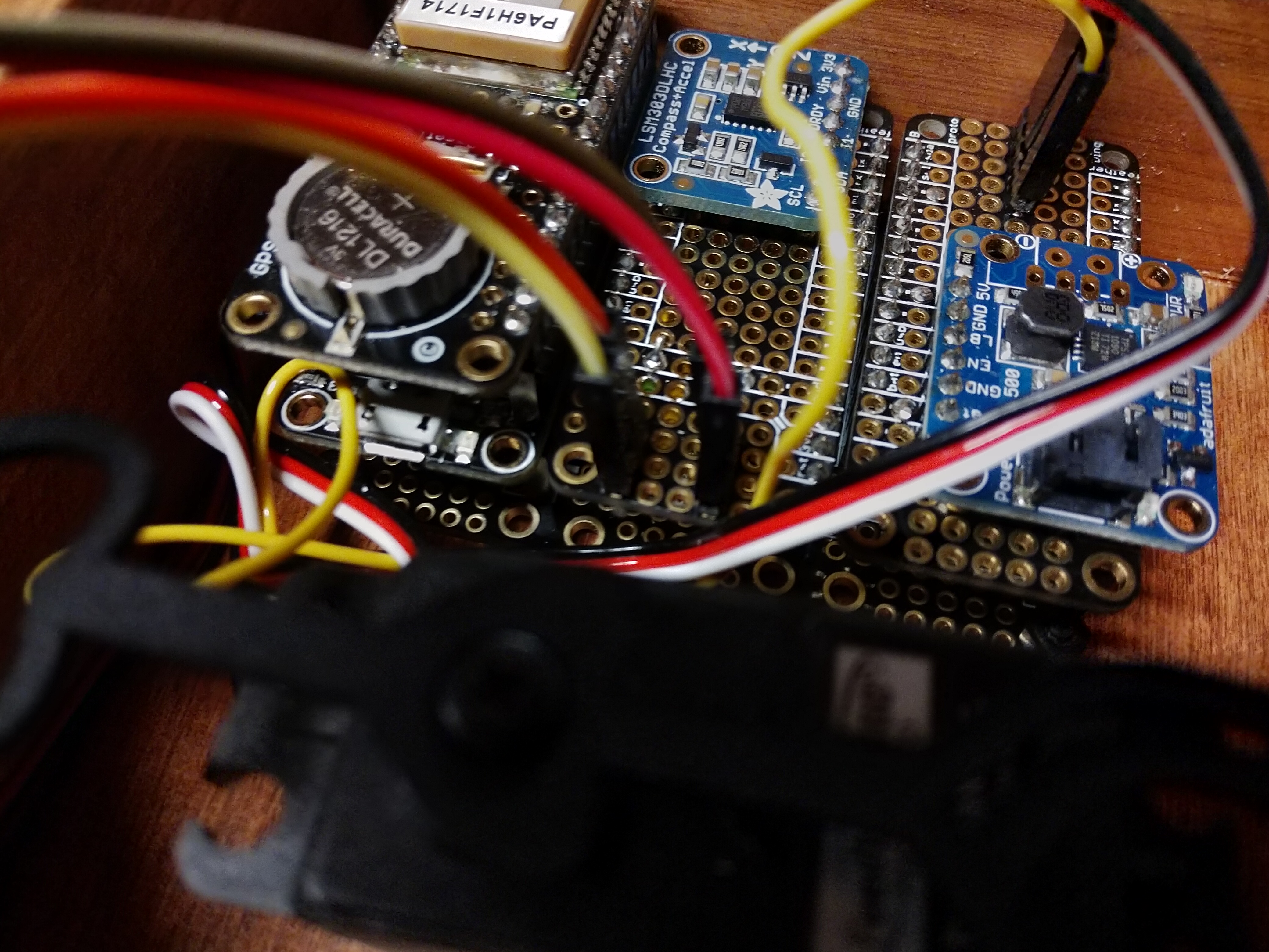
The Adafruit Feather system provided a modular way to build the project. I used a Adafruit Feather Wing Tripler to connect 4 board together. So, you are asking how did I connect 4 board with 3 connections? Well, I stacked two of them together, with the Ultimate GPS FeatherWing stacked on top of the HUZZAH32. Two FeatherWing proto boards were used to house the other electronics. One FeatherWing proto board contained the LSM303 magnetometer with leads for the smart switch and the LED. The other proto board contained the PowerBoost board and leads for the servo and the feedback wire.

Modules from top: Feather Wing tripler proto board, HUZZAH 32, Ultimate GPS feather wing with enable pin wire (blue wire), proto board with magnetometer and wiring for LED light and switch, proto board with Powerboost board and wiring for servo.
All modules assembled in box.
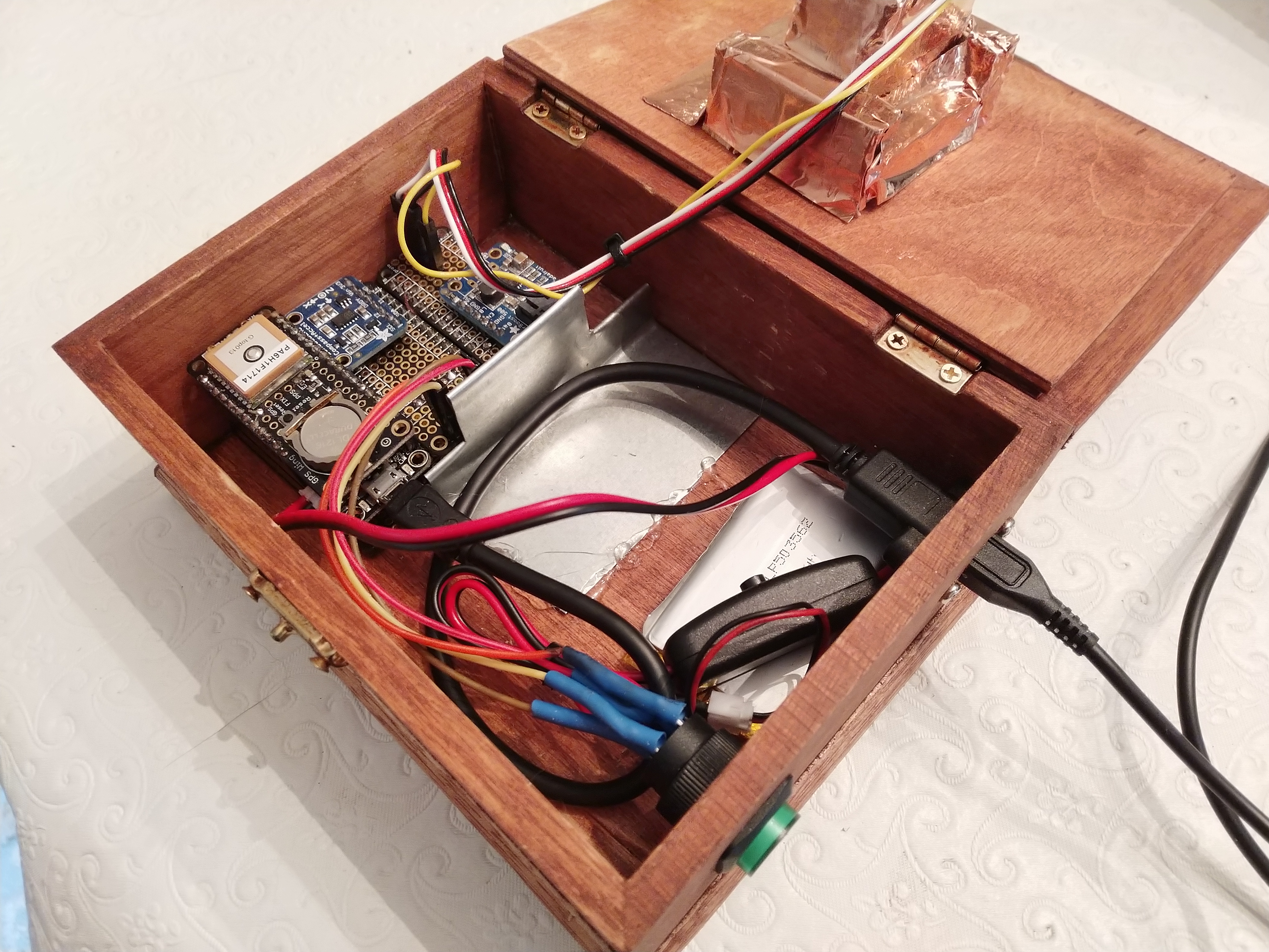
Final assembly with shielding.
One should keep in mind the servo contains magnets, so it is not a good idea to place the servo adjacent to the magnetometer board. I found this particularly true when using a small box. I added a sheet metal wall between the servo and the magnetometer for shielding, but I still found some interference. A bigger box will provide a greater distance between the servo and the magnetometer.
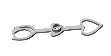
3D design of compass pointer
The compass pointer was designed in Fusion 360 and printed at Shapeways.
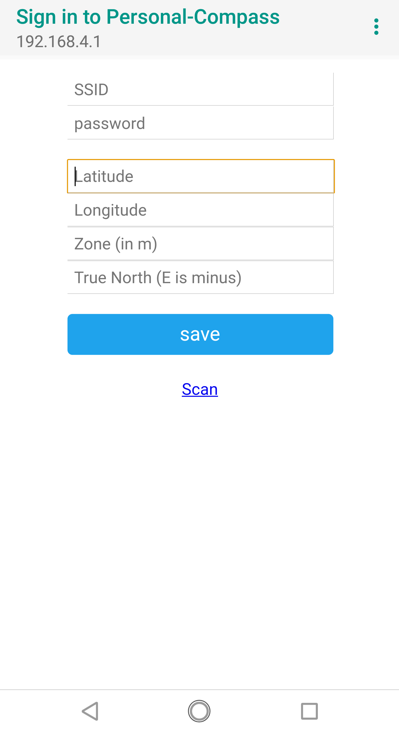
You can enter the personal compass settings from a smart phone, no hard coded location required.
Challenges
With all this greatness in using the ESP32, it is not without its hiccups. Adafruit recommends this chip for experience developers only. The processor is new and may not be supported with some libraries. I found this true in a couple of instances. For example, I found a bug in the I2C support in the ESP32 libraries. Fortunately, there was a patch available but it had not made its way yet into the official release. Also, the standard Arduino servo library does not support the ESP32 (at least not yet). The good news is that someone has written an ESP32 specific servo library that matches the API calls of the Arduino servo library (see https://github.com/jkb-git/ESP32Servo ).
Use of a continuous rotation servo with feedback was a must for this project in order to allow full rotation of the compass pointer without a complicated gear setup. Unfortunately, there are very few motors on the market that provide both continuous rotation and feedback. Adafruit sells the Parallax Feedback 360° High Speed Servo. This servo was a bit overkill for my needs but I could not find any other smaller motors. It also required 5 volts, so an Adafruit Powerboost module was added to convert the 3V battery supply to 5V that the servo could use.
Interestingly, the magnetometer provided some of the most difficult challenges of the project. First, it was noticed the compass needle moved if the device was tilted slightly up or down or rolled clockwise or counterclockwise. Research was done to find an algorithm that would take tilt and roll into consideration when calculating the magnetic north direction. The algorithm uses acceleration data in addition to the magnetometer data to calculate the adjusted magnetic setting. Fortunately, the LSM303 chip used to retrieve the magnetometer data also has an accelerometer where this data can be retrieved. I still found some compass variations with tilt and roll with the new algorithm but it was less than the original algorithm.
The other issue with the magnetometer was magnetic interference from the servo motor. There are several magnets in the servo used to rotate the motor shaft and determining the position of the shaft using a Hall effect sensor. These magnets affected the sensor’s reading of magnetic north, which I could see changing as the compass needle rotated. I added copper tape and a sheet metal wall between the sensor and the servo to help minimize the interference but a better idea would be to use a bigger enclosure where the servo and magnetometer are further away.
Improving the “Improved Personal Compass”
These ideas are not in the code but could be added for an improved “Improved Personal Compass”. With additional code, the device could handle multiple locations to avoid having to re-enter GPS coordinates for a shortlist of locations. A long press of the button could act as a switch between locations. One could also add configuration settings to use the device as a compass to magnetic or true north instead of a GPS location.